



Magnetization decision
Axial vs Diametrical Magnetization: Drawing & Design Guide
Direct answer: Axial magnetization places the poles on opposite end faces of a disc, cylinder, or ring. Diametrical magnetization places them on opposite sides across the diameter. The choice changes the useful field direction, assembly orientation, magnetizing fixture, pole reference, and inspection setup; it cannot be decided from the magnet shape alone.
The difference is the magnetic axis, not the outline
A round magnet can be magnetized in more than one direction. For an axially magnetized disc, the magnetic axis follows the cylinder axis and the two flat faces carry opposite poles. For a diametrically magnetized disc or cylinder, the magnetic axis crosses the circular section and the curved surface transitions from one pole side to the other.
The same external dimensions therefore do not guarantee the same useful field. The surrounding steel, air gap, sensor location, mating magnet, and installed orientation determine which direction fits the product.
Engineering Evidence · Direction comparison · Revision A
A direction callout is complete only when the magnetic axis is tied to a physical datum, viewing direction, polarity, delivery or assembly state, and a repeatable inspection position. A round outline does not identify the field direction by itself.
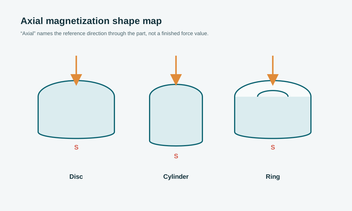
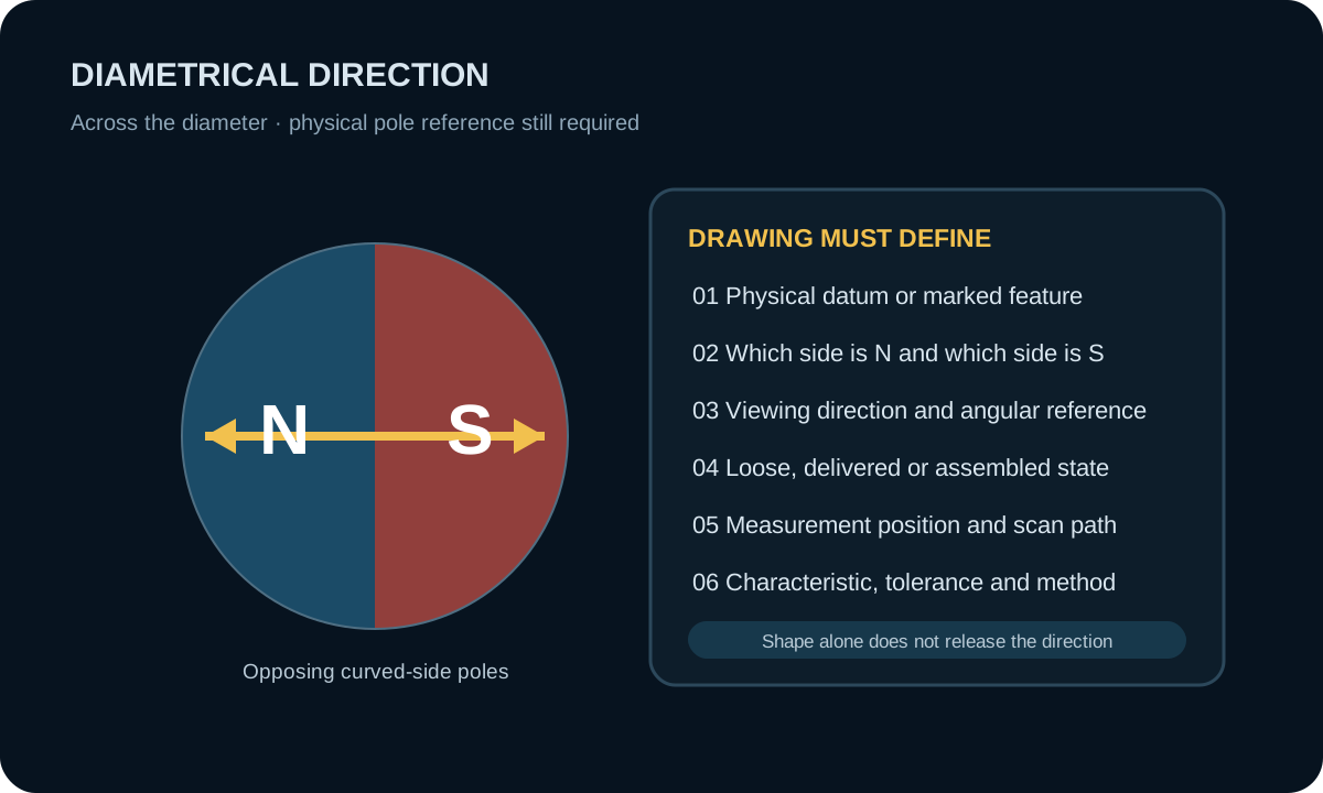
Axial and diametrical magnetization compared
| Decision point | Axial | Diametrical |
|---|---|---|
| Primary direction | Through the axis or thickness | Across the diameter |
| Pole location | Opposite end faces | Opposite side regions on the curved surface |
| Drawing reference | Axis, end face, viewing direction, and polarity when required | Angular or flat-feature datum, viewing direction, and polarity |
| Assembly concern | Axial stack, face-to-face coupling, or defined air gap | Rotational clocking, side-facing field, and retention around the reference |
| Inspection setup | Defined face, axial distance, orientation, and reference part | Defined angle, radial distance, mechanical datum, and scan path |
| Common specification error | Calling a face “north” without a physical datum | Requesting “diametrical” without defining clocking or viewing direction |
When axial magnetization may fit
- The working field or attraction is needed through the flat faces.
- The magnet is stacked, coupled, or sensed along its main axis.
- The assembly naturally controls which end face points toward the air gap.
- A face-based magnetic measurement represents the product function.
These are screening conditions, not capability guarantees. The magnetic circuit and required result still need review.
When diametrical magnetization may fit
- The useful field must point across a shaft, cylinder, or ring.
- A rotating sensor or coupling needs a side-to-side pole transition.
- The assembly contains a flat, key, mark, or datum that can control angular orientation.
- The inspection method can correlate the magnetic pole position to that mechanical reference.
For a diametrically magnetized round part, “clocking” is part of the functional definition. State the start angle or mechanical datum, the viewing direction, the intended N/S relationship, and whether the part is inspected loose, in a fixture, or in the assembly. Without those conditions, two parts can both be called diametrical and still be installed differently.
Fixture and assembly constraints
Magnetization direction changes more than the pole note. The fixture must access the intended axis or pole regions without conflicting with nearby steel, shafts, housings, adhesive, electronics, or the final retention method. Decide whether magnetization occurs before or after assembly, then verify the final assembled state when the magnetic circuit—not the loose part—protects the product function.
What the drawing must make unambiguous
- Part shape and the physical axis used as the reference.
- Axial or diametrical direction shown with an arrow or pole sketch.
- Required north-pole face or side, if polarity matters to assembly.
- Angular clocking relative to a flat, notch, key, mark, or datum for diametrical parts.
- Magnetized or unmagnetized delivery state.
- Measurement position, air gap, orientation, and acceptance characteristic.
For the broader specification context, see Magnetization Direction and Patterns. The drawing specification guide turns the same inputs into a release checklist, and the custom magnet drawing checklist keeps the requirement package reviewable for an RFQ.
Decision checkpoint
Choose the direction that produces the required field at the product’s working location and can be located, assembled, magnetized, and inspected repeatably. If the decision is being made only from a catalogue image or magnet shape, the magnetic circuit is not yet sufficiently defined.
Information to send for engineering review
- 2D drawing and a simple section of the mating magnetic circuit.
- Field, force, torque, or sensor target at a stated position.
- Air gap, nearby steel, shaft, housing, and installed orientation.
- Required pole direction, polarity, and angular reference.
- Operating temperature, assembly sequence, quantities, and evidence required.
Compare the available custom magnet material routes, review bonded NdFeB or sintered NdFeB when the route is known, then review the custom magnet engineering route and inspection approach. Send the application drawing through the custom magnet RFQ.
Engineering note: Direction feasibility and field performance depend on material, geometry, fixture route, surrounding magnetic circuit, assembly state, and test method. This article does not state a universal capability.
Frequently asked questions
What changes when axial magnetization is replaced by diametrical magnetization?
The pole locations, useful field direction, angular reference, assembly orientation, fixture design, and inspection path all change; it is not only a different drawing note.
Can the same part geometry support either direction?
Sometimes, but feasibility and field quality depend on aspect ratio, material, magnetizing fixture, required field, and whether the part is magnetized before or after assembly.