



Drawing specification
How to Specify Magnetization on a Drawing
Direct answer: Show magnetization with an arrow or pole sketch tied to named faces, datums, or an angular reference. State direction, polarity when required, pole count and sequence for multipole parts, magnetized delivery state, orientation marking, and the measurement location and acceptance characteristic. Avoid notes such as “standard magnetization” or “north side” without a physical reference.
A usable callout connects magnetic intent to the part
The drawing must let manufacturing, assembly, and inspection identify the same magnetic feature. A direction label without a mechanical reference can leave the part rotationally ambiguous. A pole sketch without a defined viewing direction can reverse the intended sequence. A field value without an air gap or measurement location cannot be reproduced.
Engineering Evidence · EM-ER-02 · Revision A
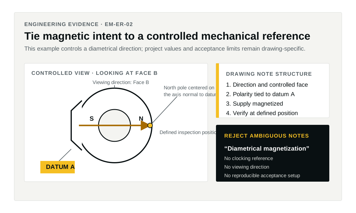
Controlled magnetization drawing example
A reproducible magnetization note combines the magnetic pattern with a named viewing direction, mechanical datum, required polarity, delivery state, and inspection position. The example below uses a diametrically magnetized ring and datum flat A to show the information relationships; it is an engineering communication pattern, not a universal customer specification.
| Control | Example relationship | What inspection must reproduce |
|---|---|---|
| Viewing direction | Looking at controlled face B | The same face and mechanical orientation |
| Clocking datum | North pole axis related to datum flat A | Angular zero tied to the physical flat |
| Delivery state | Supply magnetized | Handling and polarity verification before assembly |
| Magnetic acceptance | Defined radial position and air gap | Equipment, fixture, position, characteristic, and sampling |
Minimum drawing information by pattern
| Pattern | Show on the drawing | Common ambiguity |
|---|---|---|
| Axial | Axis arrow, opposite pole faces, polarity if assembly requires it | “Axial” without identifying the controlled face |
| Diametrical | Cross-diameter arrow and angular relation to a flat, mark, key, or datum | No rotational clocking reference |
| Radial ring | Inside/outside polarity, radial direction, and assembly state | “Radial” without stating which surface is north |
| Multipole | Pole count, pitch or angle, sequence, start reference, viewing direction | Alternating poles shown without a controlled start position |
| Arc or rotor segment | Rotor center, inner/outer radius, polarity, segment order, installed orientation | Inspecting the loose segment without assembly context |
Drawing-ready checklist
- Direction: axial, diametrical, radial, through thickness, or a controlled pole map.
- Physical reference: datum face, axis, flat, key, notch, mark, bore, or assembly feature.
- Polarity: required north and south locations when orientation matters.
- Multipole definition: pole count, pitch, sequence, transition, start position, and viewing direction.
- Delivery state: magnetized, unmagnetized, or magnetized after assembly.
- Orientation mark: type, location, permanence, and whether it is informational or controlled.
- Acceptance: measurement position, air gap, orientation, equipment or method, characteristic, and sampling.
Example callout structure
A project-specific note can follow this structure: “Magnetize diametrically along the axis shown. North pole centered on datum flat A within the approved angular relationship. Supply magnetized. Verify polarity and field characteristic at the defined radial position and air gap according to the approved inspection plan.”
This is a communication example, not a universal drawing standard. Replace every placeholder with controlled project data and align the wording with the customer drawing system.
Inspection must be specified at the same time
Polarity checks, field readings, flux measurements, pole-position scans, or functional tests answer different questions. Choose the method that protects the product. Define whether inspection occurs on the loose magnet or final assembly and how mechanical datums correlate with the magnetic result.
Review before the drawing is released
- Confirm the magnetic circuit and working position.
- Review fixture feasibility for the selected material and geometry.
- Confirm assembly sequence and magnetized handling.
- Resolve the physical reference for polarity or pole position.
- Agree the inspection characteristic and evidence.
- Freeze the note, pole sketch, and revision together.
Use the broader magnetization specification guide and the axial vs diametrical comparison where relevant. Compare magnet material routes, review fixture and manufacturing feasibility and inspection planning, or submit the drawing through the RFQ form.
Engineering note: Magnetization notes must be approved for the actual material, geometry, fixture, assembly, and inspection route. The example wording is not a guaranteed specification.
Frequently asked questions
What magnetization details belong on a drawing?
Define direction, N/S position, pole count and pitch where applicable, the mechanical reference, delivery state, magnetization before or after assembly, and the magnetic inspection method.
Should magnetic acceptance be a surface-field value only?
Not necessarily. Use the measurement that represents function: flux density at a defined point, a scan waveform, pole position, integrated flux, force, torque, or an assembly-level result.