



Bonded Magnet Manufacturer: Process, Geometry and RFQ Review
A bonded magnet manufacturer review should connect the useful magnetic result to the powder and binder system, injection-molded or compression-bonded route, geometry, inserts and interfaces, pole pattern, tooling, inspection, prototype and annual quantities, and production-release evidence. A material name or drawing alone does not establish finished performance, feasibility, price, MOQ, or lead time.
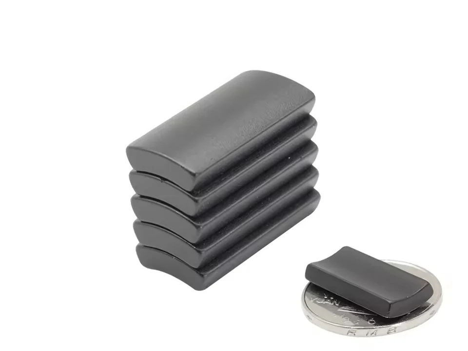
MaterialNdFeB powder with polymer binder
ProcessInjection molded or compression bonded
ShapesRings, rotors, arcs, inserts, molded forms
Main reasonShape variety, tolerance, and multipole patterns
Product
Shape freedom, integrated features, and controlled pole patterns.
Bonded NdFeB is the route for molded or compressed geometries where sintered machining would be difficult, wasteful, or unable to deliver the required multipole pattern. Tooling, binder, wall thickness, and magnetization fixture should be reviewed as one specification.
Review custom magnetic engineering and assembly capabilities
High freedom for molded forms
Multipole and radial magnetization options
Repeatable dimensions for production programs
Where it earns its place
- The part needs complex geometry, thin walls, inserts, or molded features.
- The magnetic pattern is multipole, radial, or fixture-dependent.
- Dimensional repeatability matters more than maximum energy product.
- Production volume can justify tooling and process route review.
What the design must manage
- Magnetic output is usually lower than sintered NdFeB and must be checked against the target.
- Injection vs compression route changes tolerance, tooling, and magnetic properties.
- Binder material affects temperature, chemical resistance, and mechanical behavior.
- Magnetization coils and fixture design should be planned before launch.
Bonded magnet manufacturer DFM input card
Use one controlled input set so engineering, sourcing, quality, and the manufacturer review the same finished-part requirement and production route.
| Review layer | Buyer input | Evidence to request |
|---|---|---|
| Magnetic function | Required field, force, torque, waveform, sensing, or motion result at a defined position and temperature. | Controlled circuit assumptions and representative functional verification. |
| Material and forming route | Powder or compound intent, binder and environment, injection or compression route, orientation, and secondary operations. | Proposed material data and route-specific DFM with stated limitations. |
| Geometry and interfaces | Wall sections, datums, inserts, shaft or housing fit, adhesive, assembly sequence, and critical dimensions. | Tooling and tolerance review plus dimensional and interface inspection. |
| Magnetization | Direction, pole count, pitch, sequence, physical reference, delivery state, and acceptance characteristic. | Fixture feasibility and reproducible polarity, scan, field, or functional test. |
| Program release | Prototype and annual quantity, tooling ownership, sampling, traceability, packaging, timing, and change control. | Comparable commercial scope, approved samples, inspection plan, and release evidence. |
Specification
More design freedom, with a deliberate output tradeoff.
Bonded NdFeB usually delivers lower magnetic output than sintered NdFeB, but it can reduce assembly steps and enable features such as thin walls, inserts, sleeves, and pole patterns. The correct route depends on injection molding, compression bonding, binder system, and expected volume.
Specification should define geometry, binder route, and magnetization pattern together.
| Material system | Bonded NdFeB; magnetic powder plus polymer binder selected by process and application. |
|---|---|
| Typical forms | Multipole rings, rotors, arcs, sleeves, thin-wall parts, inserts, and molded assemblies. |
| Process route | Injection molding for shape freedom; compression bonding for higher magnetic loading where suitable. |
| Magnetization | Multipole, radial, axial, or custom fixture-dependent patterns. |
| Engineering risk | Magnetic output tradeoff, tooling cost, wall thickness, binder limits, and annual volume. |
Technical Data
Bonded NdFeB material reference bands.
These ranges help compare process routes. Final performance depends strongly on powder loading, binder, part geometry, and magnetization pattern.
| Grade / Route | Br (T) | Hcj (kA/m) | BHmax (kJ/m³) | Max temp. (°C) | Density (g/cm³) |
|---|---|---|---|---|---|
| Injection molded PA | 0.35-0.55 T | 500-750 kA/m | 20-55 kJ/m3 | 100 C | 3.8-5.0 g/cm3 |
| Injection molded PPS | 0.35-0.52 T | 500-720 kA/m | 20-50 kJ/m3 | 150 C | 3.8-5.0 g/cm3 |
| Compression bonded N8 | 0.55-0.62 T | 600-800 kA/m | 50-65 kJ/m3 | 120 C | 5.5-6.0 g/cm3 |
| Compression bonded N10 | 0.60-0.68 T | 650-850 kA/m | 65-80 kJ/m3 | 120 C | 5.5-6.0 g/cm3 |
Bonded projects should confirm pole pattern, tooling economics, and annual volume before sampling.
Forms and manufacturing scope
Geometry that can do more of the assembly work.
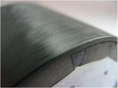
Rotors and sleeves
For small motors, pump systems, and rotating magnetic assemblies.
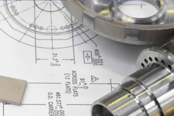
Assembly-ready parts
For components supplied with geometry, magnetization, and handling controls aligned.
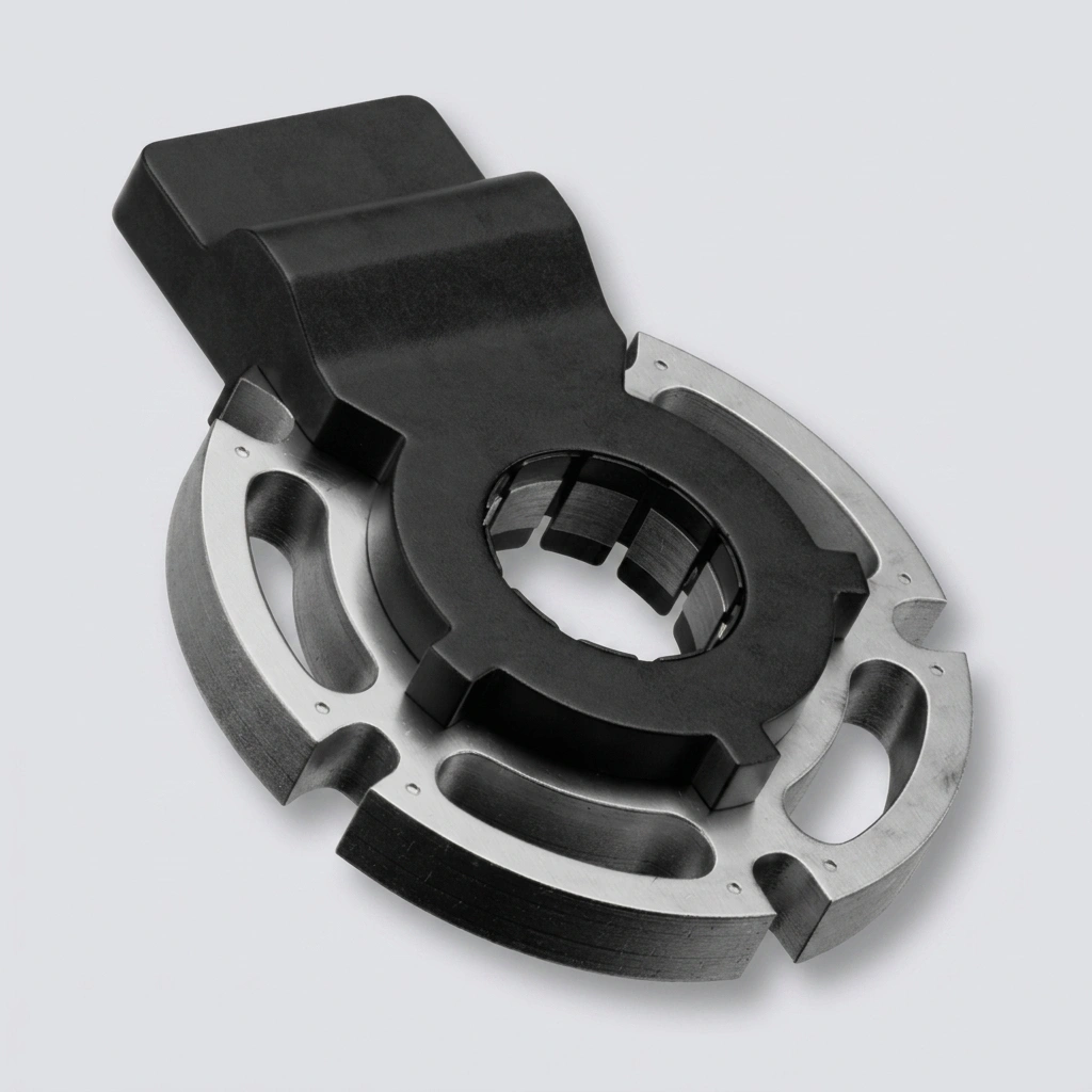
Integrated rotor systems
For molded magnetic elements developed around shafts, housings, pole patterns, and downstream assembly.
Application examples
Where shape freedom creates a better magnetic component.

Small motors
Rotors, rings, and multipole parts where shape and magnetization are linked.

Sensors and encoders
Magnetic patterns for position feedback and compact sensing packages.
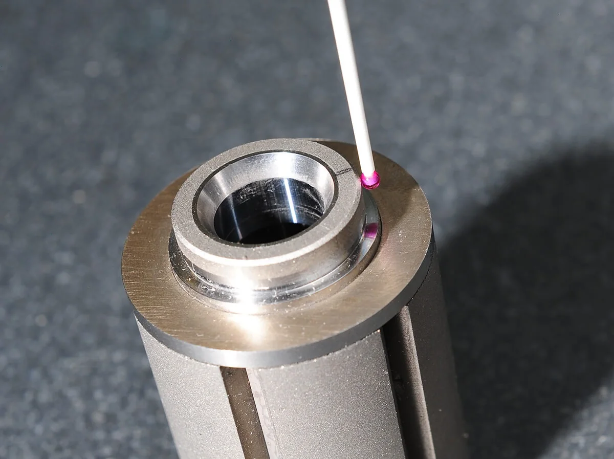
Integrated assemblies
Molded or bonded components that reduce downstream handling and alignment.
Engineering guides
Resolve the decisions that shape this material route.
Use these guides before the drawing, grade, coating, magnetization, or inspection plan becomes expensive to change.
Magnetization Direction and Patterns
Specify pole direction, pole count, physical references, delivery state, and verification logic together.
Read the guideAxial vs Diametrical Magnetization
Review how pole location, field direction, angular reference, assembly, and inspection change.
Read the guideHow to Specify Magnetization on a Drawing
Control polarity, pole map, physical reference, delivery state, and magnetic acceptance on the drawing.
Read the guidePermanent Magnet Dimensional Tolerances
Connect molded geometry, inserts, functional interfaces, tooling route, and inspection method.
Read the guideFrequently asked questions
Bonded magnet manufacturer and RFQ questions
What should be sent to a bonded magnet manufacturer first?
Provide the useful magnetic result, drawing or model, forming-route assumptions, material or binder constraints, geometry and interfaces, magnetization or pole pattern, inspection method, prototype and annual quantities, tooling expectations, and release evidence.
Should injection molding or compression bonding be selected from geometry alone?
No. Review magnetic target, powder and binder system, wall sections, inserts, orientation, pole pattern, environment, tooling, volume, secondary operations, and validation together.
Does Elite Magnets publish a standard bonded-magnet MOQ, price, or lead time?
No universal MOQ, price, or lead time is stated because process route, material, tooling, geometry, magnetization, inspection, quantity, packaging, and production stage change the commercial scope.
When should pole pattern and magnetization be defined?
Define direction, pole count, pitch, sequence, physical reference, delivery state, and magnetic acceptance before tooling and assembly are frozen because they affect fixture feasibility and inspection.
What evidence supports bonded-magnet production release?
Use the controlled drawing, approved material and route, tooling and sample evidence, dimensional and magnetic inspection, interface or assembly validation, traceability, packaging, change control, and the agreed functional result.
Related product routes