



Drawing and DFM guide
Permanent Magnet Dimensional Tolerances: Design and Drawing Guide
There is no single tolerance table that applies to every permanent magnet. Material, size, shape, forming and machining route, coating, datums, measurement method, sampling, volume, and the function of the dimension must be reviewed together. Start with the functional interface, then define the production route and reproducible inspection condition instead of assuming a generic capability number.
Why permanent magnet tolerances are application-specific
A tolerance is not only a number on a drawing. It connects a functional need to a manufacturing process and an inspection method. A dimension that controls an air gap, rotor balance, adhesive bond line, sensor position, or mechanical fit deserves different treatment from a non-critical external dimension.
Applying tight general tolerances to every feature can increase machining, grinding, inspection, yield loss, lead time, and cost without improving product performance. The goal is to control the characteristics that matter and leave appropriate process freedom elsewhere.
Material and manufacturing route shape capability
| Route | How dimensions are created | Questions for the drawing |
|---|---|---|
| Sintered NdFeB or SmCo | Forming and sintering followed by route-specific cutting, grinding, or other finishing where required | Which surfaces require finishing, what geometry is brittle, and whether coating follows machining |
| Compression-bonded magnet | Tool-defined geometry followed by cure, finishing, coating, or magnetization as required | Tooling direction, shrinkage control, flash, inserts, annual volume, and critical functional dimensions |
| Injection-molded magnet | Molded geometry with potential integrated features and process-dependent shrinkage | Draft, gates, parting line, inserts, warpage, tooling investment, and measurement strategy |
| Magnet assembly | Individual magnet dimensions plus adhesive, sleeve, hub, fixture, and assembly variation | Whether the controlled result belongs to the magnet, the subassembly, or the finished assembly |
The table describes design considerations, not guaranteed numerical capability. Each route must approve the actual material, dimensions, geometry, coating state, volume, and inspection method.
Size, aspect ratio, and brittle geometry matter
Permanent magnet materials can be brittle, and some process routes are sensitive to thin walls, long slender sections, sharp corners, narrow bridges, deep holes, slots, interrupted surfaces, and abrupt section changes. These features may affect forming, machining, chipping, distortion, coating coverage, handling, and inspection.
- Identify whether a hole or slot is truly required in the magnet or can be created in the surrounding assembly.
- Use radii, chamfers, or edge conditions that support handling and coating where the product allows.
- Avoid assuming that a tolerance proven on a simple block transfers to a thin ring or arc segment.
- Review fragile features before tooling, fixtures, or mating parts are frozen.
Start with functional interfaces and datums
A useful datum scheme reflects how the magnet locates in the product and how it can be measured. The drawing should distinguish assembly interfaces, magnetic air-gap surfaces, bond surfaces, rotational references, and non-functional surfaces.
For a ring or rotor component, bore, outside diameter, face, pole pattern, and clocking feature may interact. Concentricity or runout may be more important than separately tight plus/minus dimensions. For a sensor magnet, pole position relative to a mechanical reference may be the characteristic that protects signal accuracy.
Plus/minus dimensions are only part of the drawing
| Functional concern | Possible control | Questions to define |
|---|---|---|
| Air gap or axial stack | Thickness, flatness, parallelism, or assembly-level gap | Which surfaces form the gap and in what coated/assembled state? |
| Rotor location and balance | Bore/OD dimensions, concentricity, runout, or assembly balance | What is the rotation datum and which component controls the final result? |
| Bond line | Surface profile, gap, location, flatness, and cleanliness | What adhesive thickness and fixture condition are required? |
| Sensor position | Mechanical datum plus pole position or field-map reference | Where is the sensor, what air gap applies, and how is magnetic position verified? |
| Handling and assembly | Chamfer, edge condition, visual criteria, or packaging control | Which edges are exposed to impact or insertion loads? |
Specify whether dimensions apply before or after coating
Coating or plating adds material and may vary around edges, holes, corners, and masked areas. If a bore, thickness, air gap, or fit is critical, the drawing should state whether the dimension applies to the substrate or finished coated part.
Do not independently specify a tight finished dimension and a coating thickness without checking whether the combined requirements are manufacturable and measurable. Review the complete stack with the coating selection guide.
Inspection method belongs in the tolerance decision
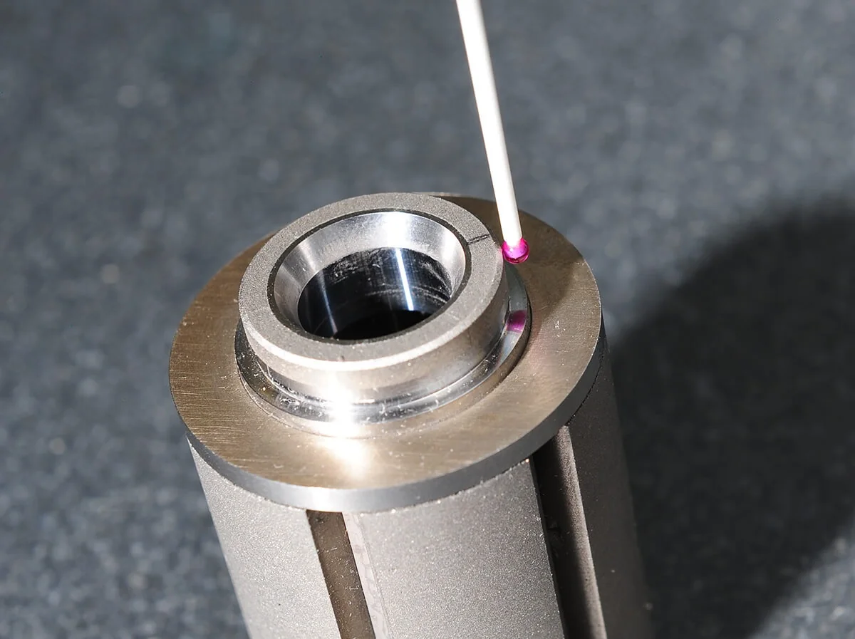
A dimension cannot be controlled consistently if the datum, equipment, contact method, measurement force, orientation, temperature, sampling, and acceptance rule remain undefined. Brittle parts and coated surfaces may also require handling methods that avoid damage during inspection.
- Define the drawing datum and measurement location.
- Identify whether the characteristic is measured on the substrate, coated magnet, or assembly.
- Use an agreed method for geometric controls such as flatness, concentricity, or runout.
- Connect sampling and reporting to the product risk and production volume.
- Resolve differences between supplier and customer measurement setups before release.
Drawing review checklist organized by functional risk
| Decision layer | Required record | Why it matters | Approval boundary |
|---|---|---|---|
| Functional interface | Air gap, fit, bond line, rotational interface or sensing location | Identifies the characteristic that needs control | Do not tighten unrelated features by default |
| Product definition | Nominal, datum scheme and required size or geometric control | Connects design intent to a reproducible drawing or model | The exact GD&T symbol and value require project review |
| Part state | Substrate, coated magnet, magnetized part, subassembly or final assembly | Prevents pre-coating and post-assembly results from being mixed | State must match the acceptance decision |
| Measurement method | Instrument or fixture, contact strategy, location, orientation and environment | Makes supplier and customer results comparable | No equipment inventory or measurement uncertainty is implied |
| Sampling and evidence | First article, sample plan, report format, revision and acceptance rule | Links the inspection record to production risk | Sampling remains project- and volume-specific |
| Open question | Owner, evidence required and decision date | Prevents an unsupported assumption becoming a drawing requirement | Keep open until the actual route is reviewed |
Sources and evidence boundaries
- ASME Y14.5: Dimensioning and Tolerancing describes the GD&T language, symbols, rules, definitions, datum references, and design-intent communication used on drawings and digital product definitions. It does not define magnet-specific manufacturing capability, inspection equipment, or numerical tolerance limits.
- Amazing Magnets: Magnet Tolerance & Geometry Limitations is used only as dated competitor coverage evidence showing how supplier content connects magnet material, process, geometry, tolerance, cost, and DFM questions. Its numerical tables, ratios, equipment, dimensions, and capability statements are excluded and are not transferred to Elite Magnets.
EM-QA-01 is an original Elite Magnets inspection-planning framework built from the approved drawing-control principles and the documented search-content gap. It does not approve a symbol, tolerance value, sampling plan, inspection route, or process capability without the actual drawing, part state, production route, measurement correlation, and project evidence.
How to prepare a tolerance-focused RFQ
- Provide the 2D drawing and, where useful, the 3D model and mating-part section.
- Mark critical-to-function characteristics instead of relying only on a general tolerance block.
- Identify material, coating, magnetization, assembly state, and annual quantity.
- Explain the functional air gap, fit, bond line, rotation, or sensing requirement.
- State which dimensions apply after coating and which surfaces may be masked.
- Share the required inspection method, sample report, customer standard, or measurement correlation need.
Send the drawing through the custom magnet RFQ or review the manufacturing and DFM route and inspection approach first.
Frequently asked questions
What tolerance can a neodymium magnet hold?
There is no responsible universal answer. Capability depends on material, nominal size, geometry, machining route, coating state, volume, datum scheme, and inspection method.
Why do magnet tolerances depend on shape and process?
Forming, sintering, molding, cutting, grinding, drilling, coating, and assembly create different variation and handling constraints. A simple block and a thin multipole ring do not share the same risk profile.
Should dimensions be specified before or after coating?
Specify the state that protects the function. Critical fits and air gaps often need finished coated dimensions, while some process controls may apply to the substrate. Make the state explicit.
Which geometric tolerances matter for ring or rotor magnets?
Concentricity, runout, flatness, parallelism, bore/OD relationship, and magnetic pole position may matter, but the correct controls depend on the assembly datum and functional risk.
How are magnet dimensions inspected?
The selected method must suit the feature, datum, part state, material, coating, tolerance, production risk, and agreed sampling plan. A named instrument or fixture does not by itself establish measurement suitability or process capability.
Engineering note: Numerical tolerance capability must be approved for the actual production route. This guide intentionally avoids presenting generic values as guaranteed capability.
Start with the permanent magnet product routes, including sintered NdFeB, sintered SmCo, and bonded NdFeB. Use custom capabilities to frame DFM and the quality approach to define inspection evidence. When the drawing, critical interfaces, part state, quantities, and acceptance needs are ready, send them through the RFQ form.
Frequently asked questions
Can standard machined-metal tolerances be applied directly to magnets?
Not safely. Brittle materials, grinding routes, thin sections, coating build, edge condition, and inspection method can make metal-part defaults costly or unstable.
Should magnet dimensions be specified before or after coating?
The drawing should explicitly state the finished condition. Critical dimensions, coating thickness allowance, masking, datums, and the measurement method must use the same definition.