



Inspection planning
How Permanent Magnet Dimensions Are Inspected
Direct answer: Magnet dimensions may be checked with gauges, micrometers, optical systems, CMMs, dedicated fixtures, or assembly-level checks. The method depends on feature size, geometry, brittleness, coating, tolerance, datum scheme, and production volume. A valid inspection requirement also defines the measured state, contact force or setup where relevant, sampling, and acceptance rule.
Inspection starts with function and datums
The equipment is not the first decision. Start with the product interface: air-gap surface, bore, outside diameter, bond face, axial stack, rotational location, or sensor reference. The datum scheme should represent how the part locates in the product and give the inspection setup a repeatable reference.
Engineering Evidence · EM-ER-03 · Revision A
Dimensional inspection correlation map
A dimensional report is comparable only when both parties use the same revision, datum interpretation, measured state, fixture logic, and edge or contact rule. Equipment names alone do not establish correlation. The controlled record should explain why the characteristic protects product function and how customer and supplier methods are reconciled before release.
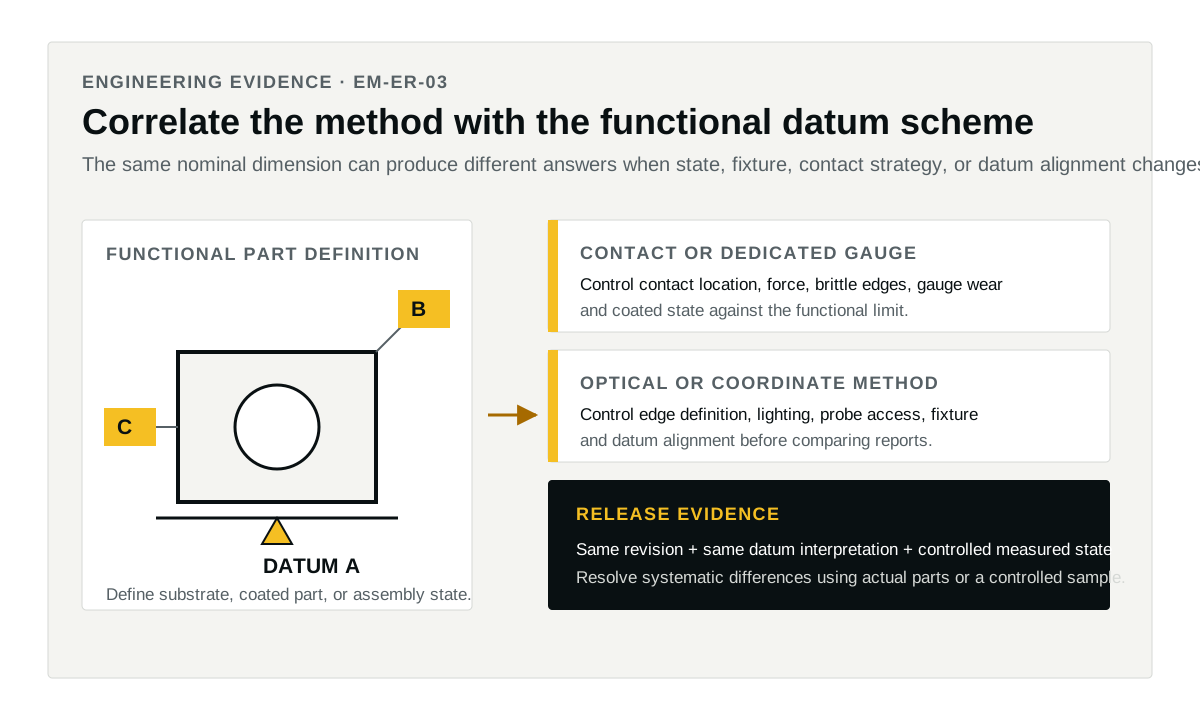
| Correlation item | Question to close | Evidence retained |
|---|---|---|
| Drawing interpretation | Are revision, units, datums, geometric controls, and coated state identical? | Controlled drawing and inspection-plan revision |
| Method setup | Are contact force, edge rule, fixture, alignment, and environment defined? | Method instruction or agreed setup record |
| Part comparison | Were the same actual parts or a controlled correlation sample used? | Paired results with part identification |
| Release decision | Were systematic differences resolved before production acceptance? | Approved correlation conclusion and responsibility |
Common methods and their roles
| Method family | May suit | Points to control |
|---|---|---|
| Go/no-go or dedicated gauge | Repeated functional limits and production screening | Gauge design, wear, datum, insertion force, and coated state |
| Micrometer or caliper-type contact method | Accessible external dimensions | Contact location, force, brittle edges, operator method, and resolution |
| Optical measurement | Small features, profiles, edges, and non-contact needs | Focus, edge definition, lighting, coating contrast, and datum alignment |
| CMM or coordinate method | Datum relationships and selected geometric controls | Fixturing, probe access, contact strategy, temperature, and program correlation |
| Assembly-level check | Final fit, gap, runout, balance, or functional location | Component stack, fixture condition, attribution of variation, and acceptance ownership |
Coating changes what is being measured
A drawing must state whether the dimension applies to the magnet substrate, the finished coated part, or an assembly. Coating can add build around faces, bores, edges, and masked transitions. Measuring the wrong state can produce a result that is accurate but irrelevant to the functional requirement.
Brittle geometry needs an appropriate setup
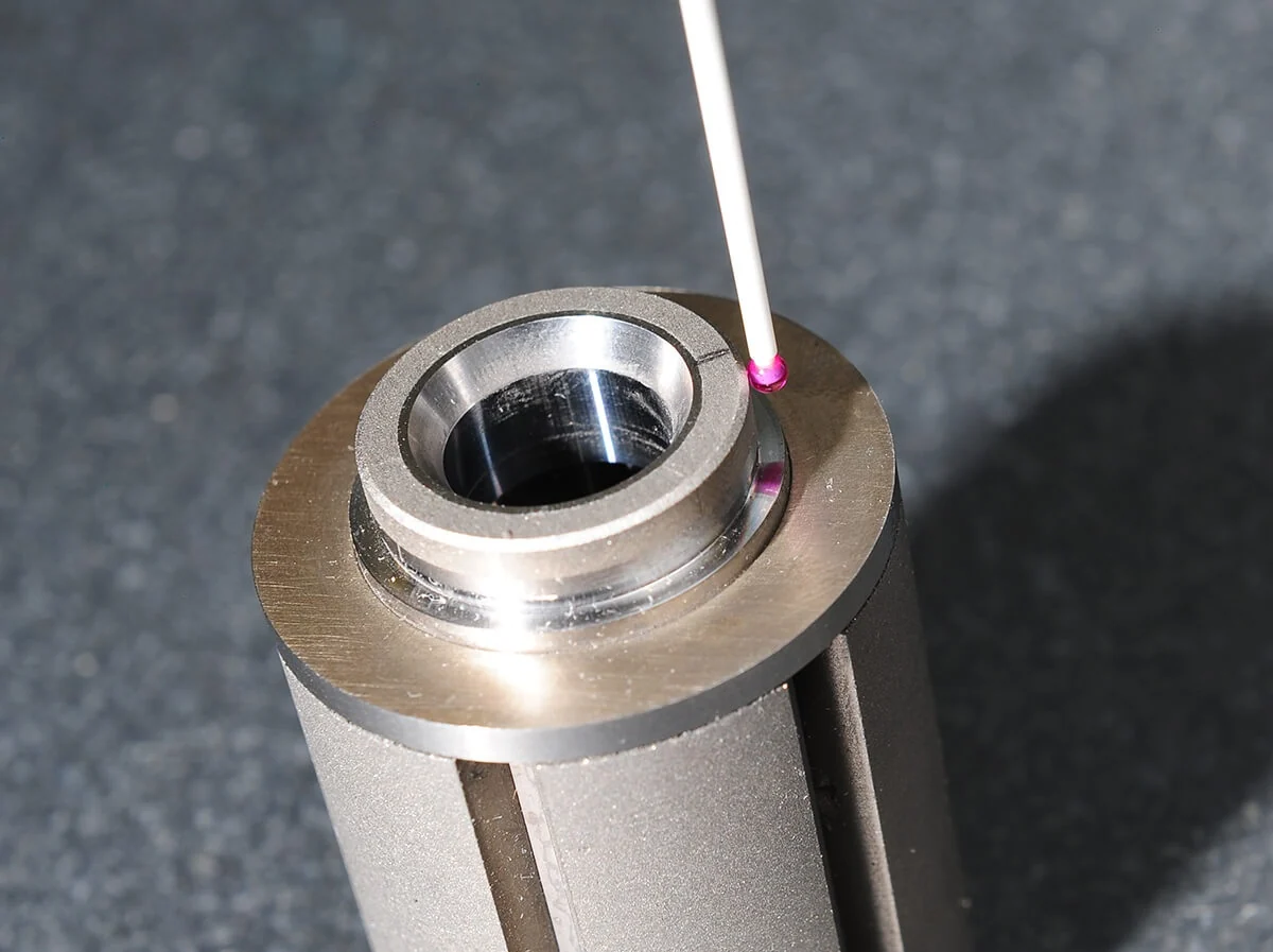
Thin rings, arcs, narrow bridges, sharp edges, and small holes may be damaged or distorted by poor fixturing or excessive contact force. Inspection planning should avoid creating chips, cracks, or false readings and should define safe handling for magnetized parts.
Correlate customer and supplier measurements
- Use the same drawing revision and datum interpretation.
- Identify coated or uncoated measurement state.
- Agree equipment family, setup, contact strategy, and environmental conditions where material.
- Compare actual parts or a controlled correlation sample.
- Resolve systematic differences before production release.
Inspection-plan checklist
- Characteristic and why it is critical to function.
- Nominal, tolerance, datum, and geometric control.
- Substrate, coated part, or assembly measurement state.
- Equipment, fixture, contact or optical strategy, and measurement location.
- Sampling frequency and any first-article or capability evidence.
- Report format, rounding convention, and acceptance rule.
- Handling and safety method for brittle or magnetized parts.
For the drawing side of the decision, see Permanent Magnet Dimensional Tolerances. Compare magnet material and product routes, review magnet quality control and inspection and the manufacturing route, or send critical characteristics through the RFQ form.
Engineering note: The methods listed are examples, not a statement that every method is available or suitable for every part. Inspection capability must be confirmed for the actual characteristic and production route.
Frequently asked questions
Which measuring method is best for permanent magnets?
It depends on the tolerance, geometry, brittleness, coating, datum scheme, and production volume. Contact gauges, optical systems, CMMs, fixtures, and functional gauges each have different strengths.
Why must the inspection datum match the drawing datum?
A different setup can create apparent variation that is not relevant to assembly. Drawing, manufacturing fixture, measurement program, and acceptance report should use correlated references.